What is FDM?
Fused deposition modeling (FDM) 3D printing, also known as fused filament fabrication (FFF), is an additive manufacturing (AM) process within the realm of material extrusion. Material extrusion is a process in which material is selectively dispensed through a nozzle or orifice. FDM builds parts layer by layer by selectively depositing melted material in a predetermined path, and uses thermoplastic polymers that come in the form of filaments.
How does FDM work?
To operate an FDM machine, you first load a spool of this thermoplastic filament into the printer. Once the nozzle hits the desired temperature, the printer feeds the filament through an extrusion head and nozzle.
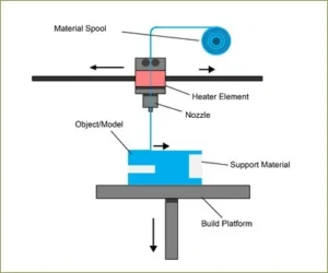
This extrusion head is attached to a three-axis system that allows it to move across the X, Y and Z axes. The printer extrudes melted material in thin strands and deposits them layer by layer along a path determined by the design. Once deposited, the material cools and solidifies. You can attach fans to the extrusion head to accelerate cooling in some cases.
To fill an area, multiple passes are required, similar to coloring in a shape with a marker. When the printer finishes a layer, the build platform descends and the machine begins work on the next layer. In some machine setups, the extrusion head moves up. This process repeats until the part is finished.
General Tolerances
- +/- 0.1016 or +/- 0.0508 per mm (+/- 0.004″ or +/- 0.002″) per inch in the XY-direction, whichever is greater.
- +/- 0.254 or +/- 0.0508 per mm (+/- 0.010” or +/- 0.002”) per inch in the Z-direction, whichever is greater.
- Theoretical maximum build volume of 610 x 915 x 915 mm (24” x 36” x 36”).
- Nylon 12 parts with thicker geometries, flat or broad parts, and parts with uneven wall thicknesses will be prone to significant deviations or warp due to variable thermal shrinkage and stress.
Wall Thickness

Holes
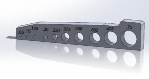
Holes for FDM should be designed with a diameter greater than 1mm (0.04”) to retain a circular shape. Orientation of holes is very important and resolution tends to be best when printed parallel to the xy-axis. This is because holes are outlined with concentric circles of filament versus staggered stops between layers. To increase the accuracy of through holes, we may drill out holes during post-processing.
Features & Recommended Size
The table below summarizes the recommended and technically feasible values for the most common features encountered in 3D printed parts.
| Feature | Recommended size |
|---|---|
| Unsupported walls | 0.8 mm (0.0315”) |
| Supported walls | 0.8 mm (0.0315”) |
| Minimum feature size | 2.0 mm (0.00787”) |
| Minimum hole diameter | 2.0 mm (0.00787”) |
Infills

A great way to save money for FDM solid parts is changing the infill type. We offers FDM parts in 3 different infill
options:
- Ultralight: Consisting of a single cross-hatch pattern throughout the parts, this infill is the most cost effective for parts that don’t need to be very strong.
- Light: This is the next best option for parts that need to retain some strength – a double cross-hatch pattern throughout the part to increases some strength but keeps the price low.
- Solid: The standard, strongest option – material is completely filled throughout the part.
Orientation

Orienting parts in FDM has an enormous impact on its overall strength and appearance, especially for fine and concentric features. A lot of designing time is spent to the optimal part orientation to reduce the likelihood of print failure and the amount of required support. Concentric features resolve best when layers print parallel to the xy-axis. Many fine features (e.g. tabs) are stronger when printed parallel to the xy-axis as well. Designing a part so that fragile and concentric features grow in the same direction will help determine the best orientation for a part to print.